Climb vs. Conventional Milling: Core Differences
Choosing between climb vs. conventional milling dictates your part’s surface finish, tool longevity, and dimensional accuracy. This guide details how directional forces impact tool deflection and chip formation, helping you optimize milling strategies for critical aerospace, automotive, and industrial components.
1. Mechanics of Tool Engagement: Climb vs. Conventional Milling
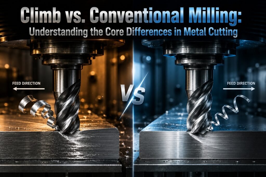
In precision CNC machining, the directional relationship between cutter rotation and table feed alters the physics of metal cutting. In climb milling (down milling), the cutter rotates with the direction of the feed. The cutting edge engages the material at the maximum thickness and exits at zero thickness. This creates a downward force that pushes the workpiece into the fixture, stabilizing the machining setup.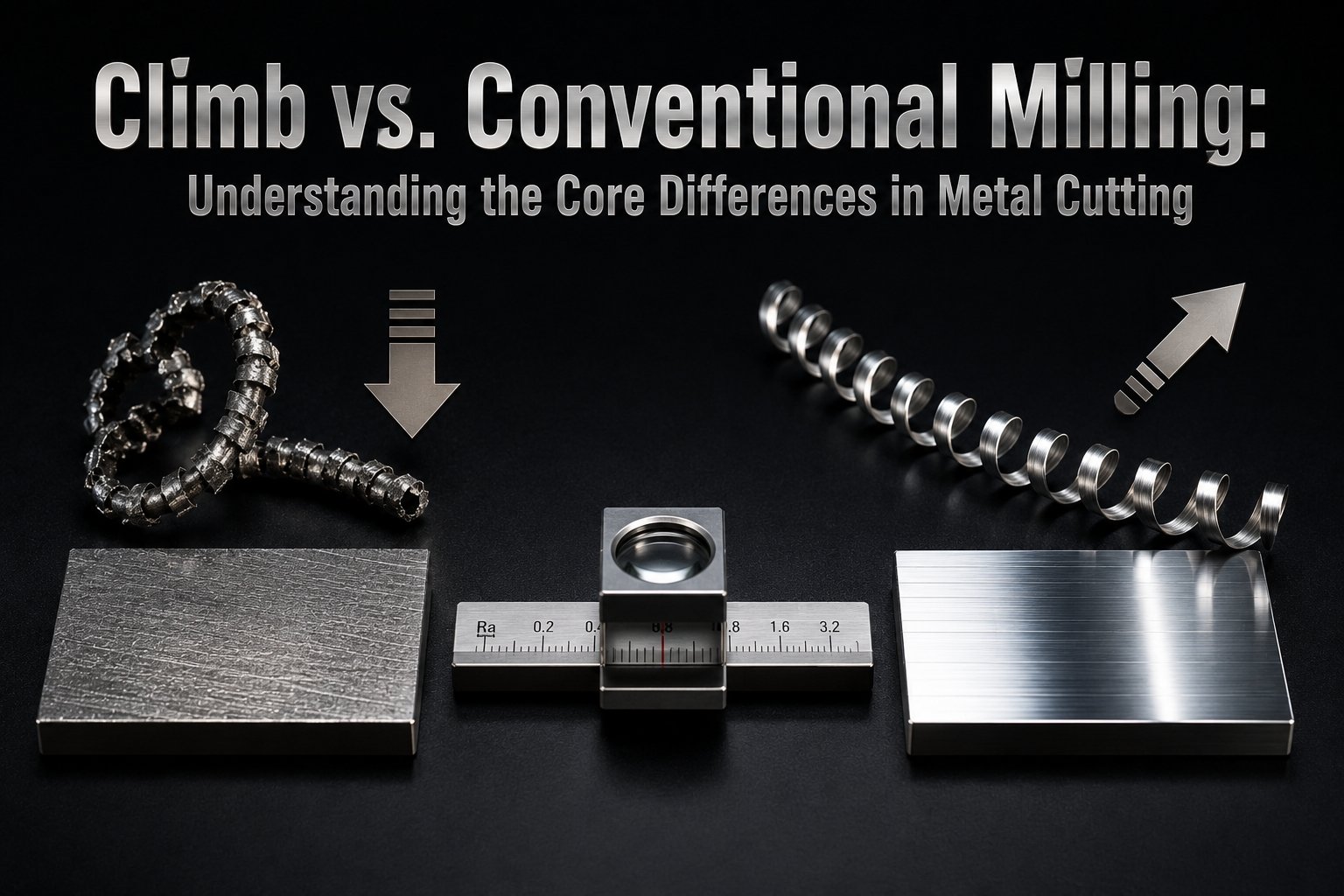
Conversely, conventional milling (up milling) features a cutter rotating against the feed direction. The tooth starts cutting at zero chip thickness, sliding across the material surface before scooping out a chip that reaches maximum thickness at the exit point. This sliding creates friction and work-hardening before actual chip formation begins.
What is Machinability?
Machinability is a relative metric evaluating how easily a material can be cut while maintaining acceptable tool life and surface finish. It factors in material hardness, tensile strength, thermal conductivity, and chemical composition. Machinability influences cutting speed ($V_c$), feed per tooth ($f_z$), and tool geometry selection. High machinability ratings indicate low cutting forces and minimal tool wear.
For industrial cnc machining service applications, understanding these mechanical differences is vital. Climb milling reduces tool wear and tool deflection, making it the preferred method for finishing operations on stable, modern CNC machinery. However, conventional milling remains critical when handling raw castings, hot-rolled steel, or surfaces with hard scale, as entering at zero thickness prevents the tool from crashing directly into a abrasive outer layer.
2. Chip Formation and Surface Finish Dynamics
Chip formation determines how heat and stress migrate during a cut. In climb milling, the “thick-to-thin” chip profile ensures that the majority of heat generated during shearing is transferred directly into the chip rather than the workpiece or the cutting tool. The immediate engagement at maximum thickness shears the metal cleanly, minimizing plastic deformation and work-hardening on the finished surface.
Conventional milling produces a “thin-to-thick” chip profile. Because the cutting edge rubs against the material before cutting begins, it generates friction and localized heat. This rubbing deforms the surface layer, leading to friction-induced work-hardening—a major issue when processing heat-sensitive materials like stainless steel or aerospace titanium alloys. This rubbing also degrades the surface finish, often requiring additional finishing steps.
| Parameter | Climb Milling (Down) | Conventional Milling (Up) | Impact on OEM Parts Machining |
|---|---|---|---|
| Initial Chip Thickness | Maximum ($f_z$) | 0.00 mm | Controls initial impact shock and rubbing. |
| Force Direction | Downward (into fixture) | Upward (pulls workpiece) | Affects fixture design and workholding rigidity. |
| Tool Deflection | Away from the cut path | Into the cut path | Directly impacts dimensional accuracy ($+/-0.01$ mm). |
| Surface Roughness ($R_a$) | 0.4 to 1.6 μm (Lower) | 1.6 to 3.2 μm (Higher) | Determines if secondary grinding is necessary. |
| Backlash Sensitivity | High (Requires eliminator) | Low / Immune | Crucial for older manual mills vs. modern CNC setups. |
When producing high-precision oem parts machining, surface integrity is non-negotiable. Experienced machining suppliers utilize climb milling for final profiles to consistently achieve surface roughness values below 1.6 μm $R_a$. For complex geometries requiring optimized paths, contact us for an engineering review: Request a CNC Machining Quote.
3. Material-Specific Strategies in Precision Manufacturing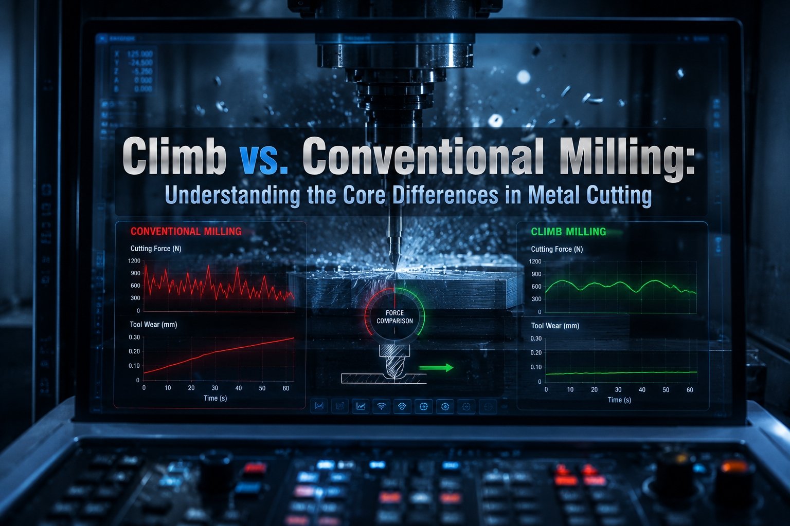
Material properties dictate whether climb or conventional milling yields the best tool life and geometric accuracy. Aluminum machining exhibits high machinability, allowing high feed rates and cutting speeds. Climb milling is preferred here because it minimizes the built-up edge (BUE) common in sticky materials, ensuring crisp edges on complex electronics enclosures or aerospace bulkheads.
When executing stainless machining or working with superalloys, the thin-to-thick profile of conventional milling can cause rapid work-hardening, accelerating tool notch wear. According to machining standards outlined by organizations like the American Society of Mechanical Engineers (ASME), minimizing tool dwell time and rubbing on work-hardening alloys is essential for predictable tool life. Therefore, climb milling is the primary choice for stainless steels, provided the setup is rigid.
However, brittle or scaled materials require selective conventional paths. For example, cast iron machining often benefits from conventional milling during roughing stages. Because cast iron features a hard, abrasive outer skin from the casting mold, a climb-milling cutter would strike this abrasive scale immediately upon engagement, causing micro-chipping of the carbide insert. Conventional milling allows the tooth to enter beneath the scale in clean material, lifting the scale off from underneath.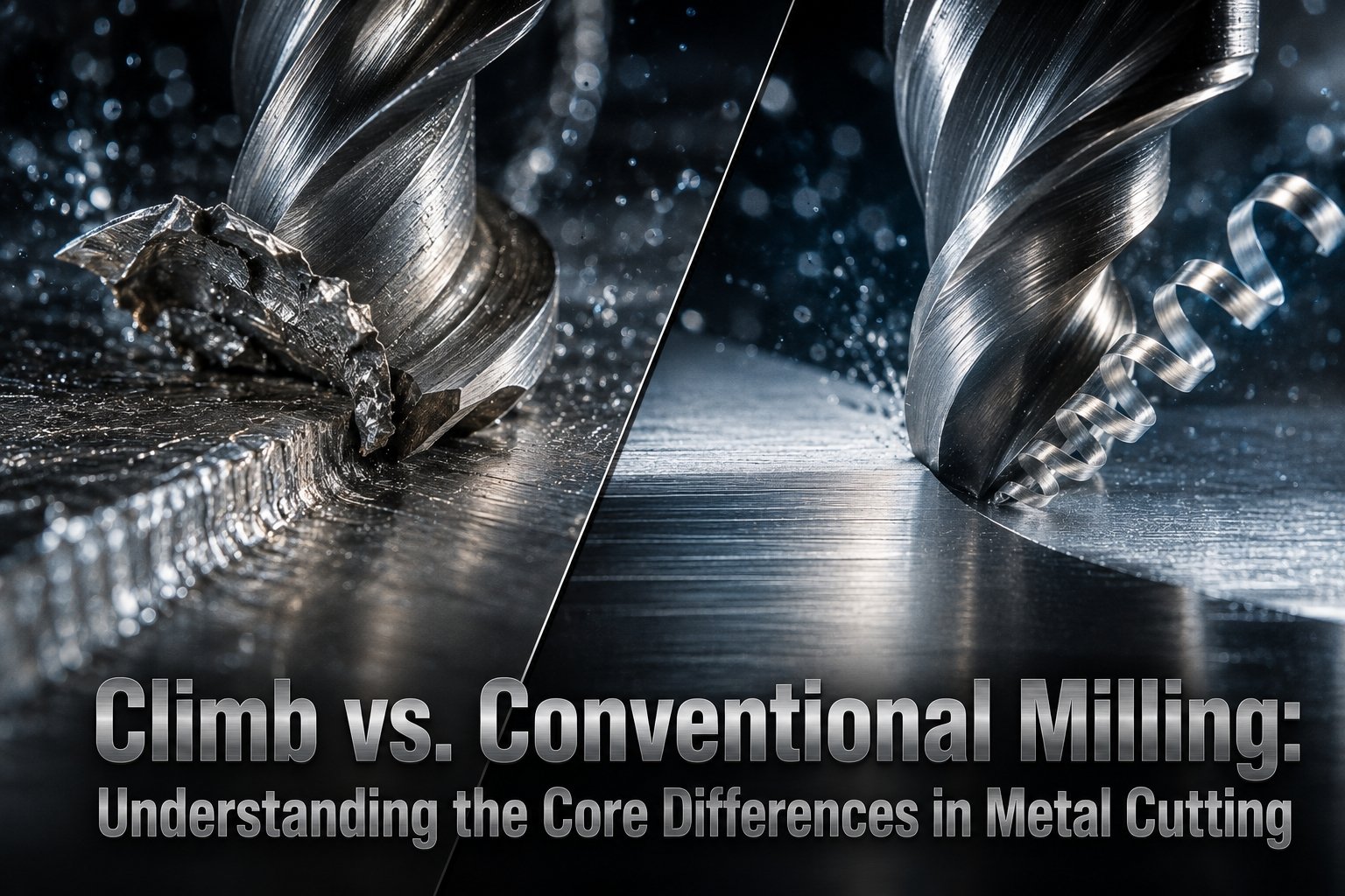
For non-metals, such as acrylic cnc service and nylon cnc machining, climb milling prevents chipping and melting. Acrylic is prone to stress-cracking; the clean downward shearing force of climb cutting minimizes structural fractures. In automated machining centers, matching tool paths to specific material characteristics prevents scrap and ensures consistent tolerances across mass production lots.
4. Tool Deflection, Backlash, and Workholding Rigidity
Tool deflection directly influences structural tolerances. In climb milling, the vector of the cutting force is directed away from the finished surface. If the tool deflects under high wing loads, it pushes away from the final part dimensions, leaving a small amount of extra material that can be removed in a subsequent finish pass. In conventional milling, the cutting force vector pulls the cutter *into* the workpiece, which can cause gouging if the tool or part deflects excessively.
Backlash is a critical factor when selecting your milling method. Climb milling pulls the workpiece into the cutter, meaning any play or backlash in the table’s lead screw can cause the table to be sucked into the tool. This sudden jump can break the cutter or damage the workpiece. Modern CNC machines use recirculating ballscrews with preloaded nuts to eliminate backlash, making climb milling safe and efficient. On older or manual machines without backlash eliminators, conventional milling is required because the cutting forces oppose the table feed, keeping the lead screw engaged against its flank.
Workholding design must account for these forces. Climb milling pushes the part down into the machine table or vise, requiring less clamping force to prevent lateral shifting. Conventional milling lifts the part up and away from the table, requiring rigid fixtures to counter the upward forces, particularly during heavy roughing passes in large cnc machining operations.
5. Advanced Applications: Multi-Axis and Automated Production
The integration of five axis machining has expanded tool path options. In 5-axis profiles, the cutter can tilt relative to the surface, altering the effective tool radius and cutting velocity. Here, maintaining a true climb-milling path requires sophisticated CAM algorithms, as the contact point shifts across the tool’s ball-nose or bull-nose radius. Proper execution prevents surface variations across complex, sculpted geometries like aerospace impellers or structural car parts machining.
In rapid cnc machining and prototype machining environments, automated machining software defaults to climb milling for its superior surface finish and predictable tool wear patterns. This consistency allows engineers to accurately simulate tool life via digital twins, which is crucial for high-speed automated lights-out manufacturing where a single premature tool failure can stop an entire production line.
Whether utilizing a cnc lathe machining center with live tooling, a high-speed cnc screw machining line, or large-scale sheet metal working equipment paired with laser cut machining, selecting the proper cutting path impacts your production costs. By optimizing tool paths for material characteristics, machining facilities can balance speed, surface quality, and tool longevity to provide cost-effective prototyping and scalable mass production.