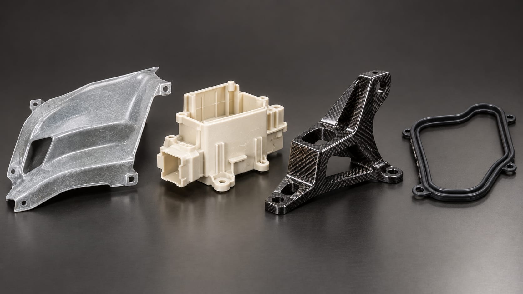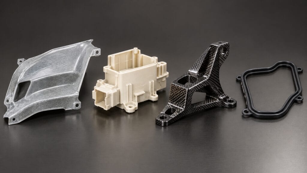

Compression molding (see the process overview on Wikipedia) is a high-pressure forming process in which a pre-measured charge of material — usually a fiber-reinforced thermoset like SMC or BMC — is placed into an open, heated mold cavity, then squeezed shut under 15–30 MPa of clamp force until the resin cross-links into a rigid part. It is the process behind automotive hoods, EV battery covers, switchgear housings, and Class A exterior panels: strong, heat-resistant, electrically stable, and cheaper to tool than injection molding for anything larger than a shoebox.
The reason most buyers get this wrong is that they compare compression molding to injection molding on piece price alone. The real decision lives in three places: tooling cost, cycle time, and whether your geometry can actually be molded without warping. This guide covers all three, plus the part nobody talks about — the mold itself, which is CNC-machined, and which is usually what fails first.
Key Takeaways
- Compression molding is the thermoset process. SMC, BMC, phenolic, epoxy, and rubber all run here; unfilled thermoplastics almost never do.
- Cycle time is 1–5 minutes, versus 10–60 seconds for injection. That gap sets your break-even, usually somewhere between 5,000 and 10,000 parts.
- Tooling runs roughly $1,000–$80,000, against $25,000–$250,000+ for comparable injection molds. The tool is the reason compression wins at low and mid volume.
- Tolerance is driven by shrinkage, not by the machine. Plan on ±0.13 mm per 25 mm, and tighter only on features you can compensate in the cavity.
- Abrasive SMC eats mild-steel tools. Shear edges and flash lands need hardened tool steel, or the mold dies at a few thousand shots.
What Is Compression Molding?
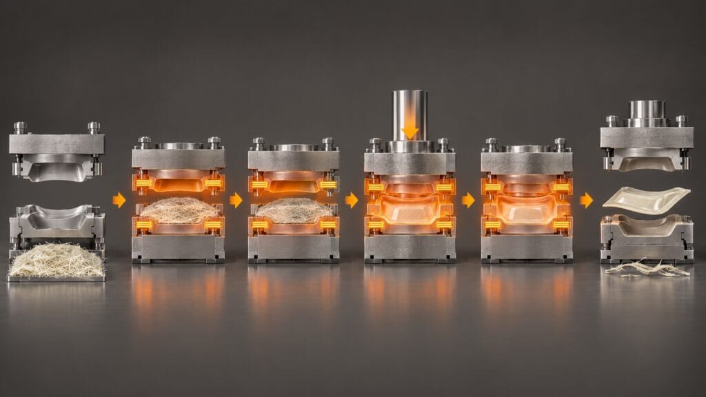
Compression molding is a closed-mold, open-cavity process. Unlike injection molding, there is no runner, no gate, and no screw pushing material through a nozzle. The material is loaded directly into the cavity and displaced by the closing press.
That single design difference explains most of its behavior:
- No shear on the fibers. Long glass or carbon fibers (12–50 mm) survive the process intact, which is why compression-molded SMC reaches 60–120 MPa tensile strength where BMC injection typically lands at 30–60 MPa.
- No delivery system to waste. Material utilization runs 90–95%, which matters enormously with carbon fiber at $30+/kg.
- Slow, bulk flow. Material spreads rather than flows, so complex undercuts and thin walls are hard, and charge placement becomes a process variable in its own right.
The six steps of every cycle
- Charge preparation. SMC sheet is cut and stacked to a weighed pattern; BMC is extruded into a preform; rubber is cut into blanks. Charge weight controls part thickness and flash volume — get it wrong and you get short shots or a flash ring.
- Mold heating. Cavity and core are held at 135–160 °C for SMC, typically by cartridge heaters or hot oil.
- Loading. The charge goes into the open cavity, positioned so flow reaches thick sections first. This is still largely manual on most presses.
- Closing and pressing. The press closes at a controlled speed, then holds 15–30 MPa. Closing speed matters: too fast and the charge traps air, too slow and the resin gels before fill completes.
- Cure. The exothermic cross-linking reaction runs 60–180 seconds for 2–3 mm walls, longer for thick sections.
- Demold and deflash. Part comes out hot, is trimmed at the flash line, and often needs secondary machining for holes, slots, and locating features.
The Materials That Actually Get Compression Molded
| Material | Fiber | Typical wall | Cycle | Where it goes |
|---|---|---|---|---|
| SMC (sheet molding compound) | 25–35% glass, 12–50 mm | 2–12 mm | 60–180 s | Body panels, battery covers, underbody shields |
| BMC (bulk molding compound) | 15–25% glass, 3–12 mm | 2–6 mm | 60–120 s | Switchgear, insulators, motor housings |
| CF-SMC (carbon) | 30–50% carbon | 2–8 mm | 90–240 s | Aerospace brackets, motorsport, premium EV |
| GMT / LFT (thermoplastic) | 20–40% glass | 1.5–4 mm | 60–120 s | Semi-structural automotive, recyclable parts |
| Phenolic / epoxy | Filler dependent | 3–20 mm | 120–300 s | High-temp under-hood, chemical process |
| Rubber (EPDM, NBR, silicone) | None | 2–25 mm | 3–15 min | Seals, gaskets, vibration mounts |
Two things worth flagging. First, GMT and LFT are thermoplastics — they are compression molded, but they consolidate rather than cure, which makes them recyclable and faster. They are the reason “compression molding is only for thermosets” is an outdated claim. Second, rubber dominates cycle time — a thick EPDM seal can sit in the press for 15 minutes, and that economics is completely different from an SMC panel.
You can also compression mold PEEK and PEI for small, high-value medical and aerospace parts, but at that point you are usually better served by machining the part from stock. See our plastic machining capability for that route.
Compression Molding vs Injection Molding
The comparison that actually decides projects:
| Dimension | Compression Molding | Injection Molding |
|---|---|---|
| Cycle time | 60 s – 5 min | 10–60 s |
| Clamp pressure | 15–30 MPa | 30–150 MPa |
| Tooling cost | $1,000 – $80,000 | $25,000 – $250,000+ |
| Best volume | 50 – 10,000 parts | 5,000 – 1,000,000+ |
| Max part size | up to 2 m × 4 m | typically under 500 × 500 mm |
| Fiber length | 12–50 mm | 3–12 mm (screw shear limits it) |
| Wall thickness | 2–12 mm, thick sections fine | 1–4 mm, thin walls preferred |
| Detail and undercuts | Limited | Excellent |
| Gate marks / runners | None | Present |
| Flash and trimming | Always present | Minimal |
The break-even calculation is simple arithmetic. A compression tool at $20,000 versus an injection tool at $120,000 saves you $100,000 up front. If the compression part costs $0.30 more per unit in cycle and labor, that $100,000 buys you 330,000 parts of runway. Below roughly 10,000 units a year, compression almost always wins. Above 300,000, injection’s cycle advantage compounds and the answer flips.
There is a second, less obvious factor: part size. Once your part exceeds roughly 500 × 500 mm, injection tooling cost and press tonnage escalate steeply. A 1.2 m SMC roof panel has no realistic injection equivalent. Size, not volume, is often the real driver.
Compression vs Transfer Molding vs RTM
- Transfer molding — material is pushed from a transfer pot through a sprue into a closed cavity. Better for intricate detail and encapsulated inserts; higher tooling cost, more material waste in the cull.
- RTM / VARTM — liquid resin is injected into a dry fiber preform in a closed mold. Lower pressure, cheaper tooling, but much longer cycle (10–60 min) and higher labor.
- Compression molding — best balance of strength, cycle time, and tooling cost for medium-to-large structural parts.
A peer-reviewed study of hybrid GMT brake pedals reports 35% mass reduction versus steel (see the Polymers 2025 paper). A useful rule: if the part has long fibers and needs to be strong, compression. If it needs fine detail and small size, transfer or injection. If it’s a large shell at low volume, RTM.
Design Rules That Decide Whether the Part Works
Compression molding punishes bad geometry more than injection does, because material spreads rather than flows.
| Rule | Specification | Why |
|---|---|---|
| Uniform wall | Keep variation under 20% | Thick sections cure faster (exotherm) and shrink differently — that’s warpage |
| Thickness transitions | Taper 3:1 or gentler | Abrupt changes create stress concentration and cure gradients |
| Draft angle | 1–3° minimum | Release without scuffing the Class A surface |
| Inside radii | ≥ 25–50% of nominal wall | Sharp corners concentrate stress and block flow |
| Ribs | Base width 60–80% of wall, height:width ≤ 3:1 | Ribs beat thick walls for stiffness without cure penalty |
| Shrinkage allowance | 0.1–0.3% (filled phenolic), 0.5–1.0% (unfilled polyester) | Mold cavity must be cut oversize by this amount |
| Charge placement | Symmetric parts: centered. Varying walls: bias toward thick | Controls flow path, knit lines, and fiber alignment |
The single most common design failure we see is asymmetric charge placement on a large panel. The flow front reaches one edge before the other, fiber orientation ends up directional instead of random, and the part bows. Fixing it is rarely a mold change — it’s a charge pattern change and a re-cut cavity with compensation.
Tolerances You Can Actually Hold
Compression molding tolerances are governed by shrinkage, mold deflection under clamp force, and flash-line mismatch — not by machine accuracy.
| Dimension | Achievable | Notes |
|---|---|---|
| General tolerance | ±0.13 mm per 25 mm | Industry-standard per-inch rule |
| Low-shrink systems | ±0.08 mm per 25 mm | Low-profile resin, well-controlled cure |
| Across the parting line | ±0.25 mm | Flash-line mismatch dominates |
| Wall thickness | ±0.3 mm | Charge weight consistency |
| Flatness on a 900 mm panel | 0.5–1.5 mm | Warpage, not machining |
| Molded-in inserts | ±0.15 mm | Insert location in the cavity |
When a drawing asks for ±0.1 mm across a 300 mm BMC housing wall, that tolerance does not exist in the process — and no honest molder will promise it. The right answer is usually mold the feature 0.3 mm proud and machine it after demold. That is a post-mold CNC operation, and it turns an impossible tolerance into a routine one.
Tooling: Where the Money and the Risk Sit
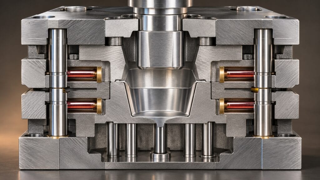
A compression mold looks simple next to an injection mold — no runners, no gates, no cooling circuits — but it has its own critical geometry, and every one of those features is cut on a CNC machine.
Anatomy of a compression mold:
- Cavity and core — the part surfaces, cut oversize by the shrinkage allowance.
- Shear edge — the vertical land where cavity and core meet. This is the hardest feature to make right: typically 0.02–0.05 mm clearance, and it determines both flash thickness and tool life.
- Flash land — a controlled flat outside the shear edge that lets excess material escape without blowing the mold open.
- Guide pins and bushes — alignment across the parting line, which directly sets the ±0.25 mm parting-line tolerance.
- Heating provisions — cartridge bores or oil channels, bored to ±0.1 mm so the heater makes contact.
- Ejection — pins or a stripper plate, sized to the part’s green strength.
Mold materials:
| Material | Hardness | Tool life | Use |
|---|---|---|---|
| P20 / 1.2311 | 30–34 HRC | 2,000–10,000 shots (SMC) | Prototype, low volume, BMC |
| 718 / 1.2738 | 32–36 HRC | 10,000–30,000 shots | General production |
| H13 / 1.2344 (hardened) | 48–52 HRC | 50,000–100,000+ shots | High-volume SMC, abrasive CF-SMC |
| Aluminum 7075 | — | 500–2,000 shots | Bridge tooling, < 100 parts |
The failure mode worth knowing: SMC is abrasive. Glass fiber at 30% by weight, sliding across a shear edge 50,000 times, will erode unhardened steel. We have seen P20 shear edges wash out by 3 mm within a few thousand shots, at which point flash thickness doubles and the part no longer trims cleanly. Nitriding the shear edge, or cutting it in hardened H13 from the start, is the difference between a tool that lasts a month and one that lasts three years.
Cutting the shear edge itself is precision milling work — typical tolerance ±0.01 mm on the land width, with the closing clearance held across the full perimeter. This is exactly the class of work our mold making services are built around, and the reason we machine mold steel on 5-axis centers rather than 3-axis with re-fixturing.
Where CNC Machining Fits After the Press
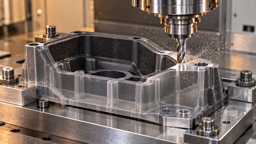
Compression molding gets you 90% of a part. The last 10% is almost always machined:
- Trimming and deflashing — CNC trimming fixtures with the part’s net profile, so the flash line is cut consistently instead of hand-ground.
- Holes and slots — molding a clean 6 mm hole in SMC is unreliable; drilling or interpolating after demold holds ±0.05 mm.
- Locating features and datums — every tolerance-critical surface on a molded part should be machined, because it establishes a real datum instead of a molded one.
- Thin-wall and precision pockets — features below 2 mm or tighter than ±0.2 mm belong in the machine, not the mold.
- Insert installation and assembly prep — counterbores, thread prep, and mating surfaces.
This is the practical overlap between molding and machining, and it’s where a CNC partner adds value rather than just quoting a press. See our CNC parts machining page for secondary-operation capability.
The Cost Model: What Actually Drives Piece Price
| Cost line | Share of piece price | Lever |
|---|---|---|
| Material | 30–45% | Charge weight discipline, scrap rate, fiber content |
| Press time | 20–30% | Cycle time, cavitation, press utilization |
| Labor | 10–20% | Manual charge loading is the bottleneck |
| Tooling amortization | 10–20% | Shot life, cavitation |
| Secondary ops | 5–15% | Trimming, machining, coating |
A worked comparison makes the economics concrete. A 400 × 300 × 3 mm housing at 100,000 units per year:
| Line item | BMC compression | ABS injection |
|---|---|---|
| Tool steel | P20, ~$5,800 | H13 hardened, ~$9,400 |
| Press rate | $21/h (400 t) | $25/h (380 t) |
| Material | $1.30/kg, 0.65 kg | $1.89/kg, 0.38 kg |
| Cycle | 120 s | 45 s |
| Manual handling | 0.8 min | 0.1 min |
| Piece cost | ~$1.68 | ~$1.61 |
Cost parity at 100,000 units, with a $3,600 tooling advantage on the compression side. Above 300,000, injection pulls 8–12% ahead on cycle alone — unless the press runs multi-cavity or servo-driven fast cycles, which closes most of that gap.
Industries and Applications
- Automotive and EV — hoods, fenders, trunk lids, roof panels, battery enclosures, underbody shields, brake pedals. SMC delivers 30–40% mass reduction versus steel at comparable stiffness. See our automotive machining work for the post-mold side.
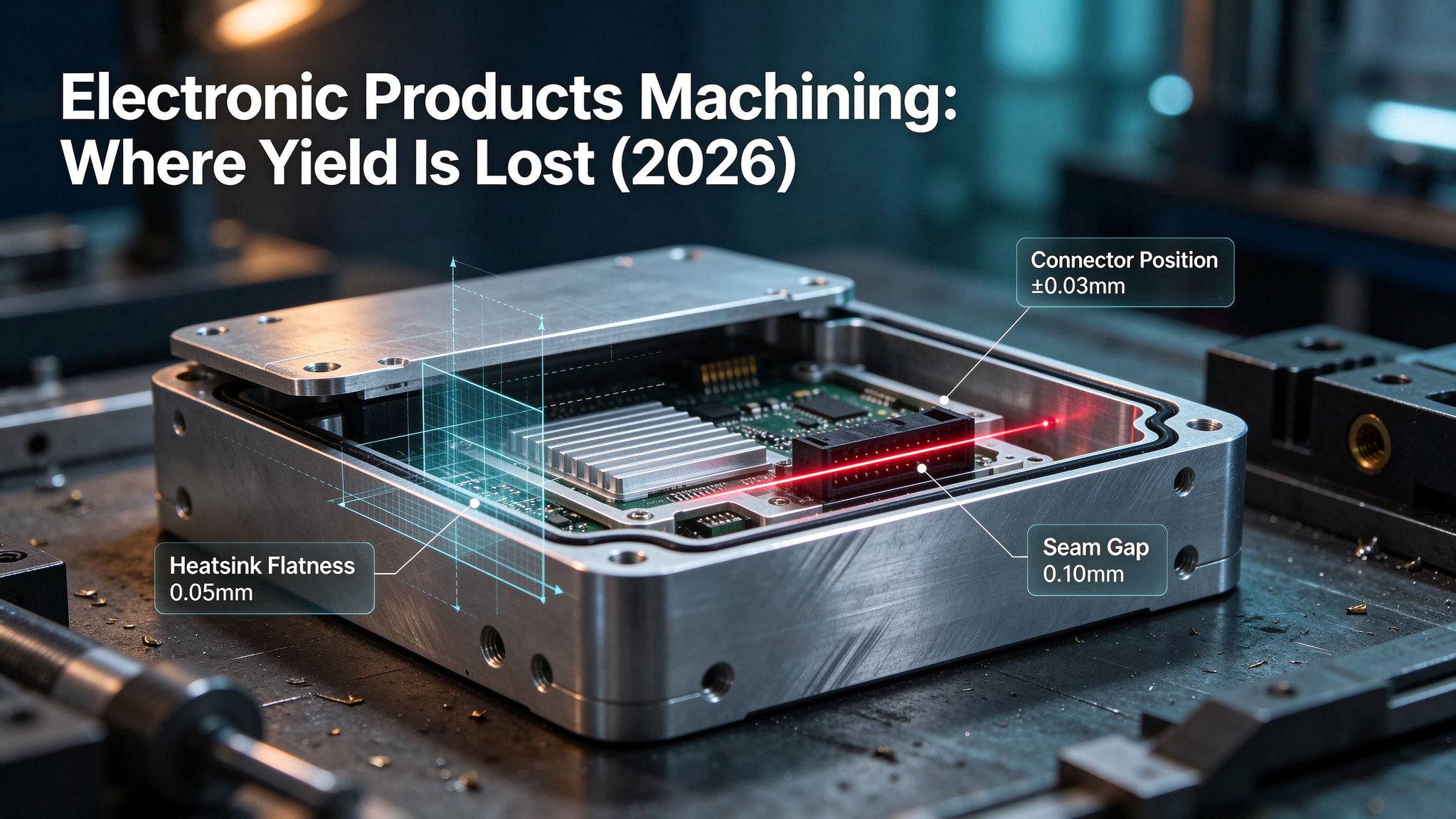
- Electrical and electronics — switchgear housings, busbar insulation, insulators, terminal blocks, motor covers. UL 94 V-0 grades are standard, and dimensional stability across thermal cycling is the design driver. Our electronics machining page covers the precision features molded parts can’t hold.
- Aerospace — interior panels, ducting, seat structures, secondary brackets. Flame retardancy plus weight.
- Industrial — pump housings, valve bodies, chemical equipment enclosures, where corrosion resistance and thick walls matter more than cosmetics.
- Consumer and appliance — large shells, tubs, and housings where tooling cost dominates the business case.
- Medical — housings and equipment frames in epoxy and phenolic, usually with machined locating features.
Sourcing Compression Molding from China: Five Checks
- Press tonnage and bed size match your part. A 400 t press with a 1 m bed cannot make a 1.2 m panel, whatever the quote says.
- In-house mold making, or at least CNC mold capability. Shops that outsource tooling lose control of the two variables that decide part quality — shrinkage compensation and shear-edge clearance.
- Charge weight control. Ask how they weigh and pattern the charge. If the answer is “the operator judges it,” your wall thickness tolerance is a wish.
- Material certificates and fiber content verification. SMC is sold by areal weight and resin content; a 25% fiber sheet quoted as 35% changes strength by roughly 40%. Ask for the batch test report.
- Secondary machining in the same building. Trimming, drilling, and datum machining done by a third party is where tolerance and schedule both slip.
We run mold making and precision machining out of our 2,000 sqm factory in Dongguan — compression mold cavities, cores, shear edges, inserts, trimming fixtures, and post-mold machining, from prototype to production, no MOQ.
Send your part drawing or mold specification — DFM feedback within 12 hours →
Five Mistakes That Sink Compression Projects
- Specifying injection-molding tolerances on a molded part. ±0.1 mm across a 300 mm wall is not a compression tolerance; plan a machining operation instead.
- Ignoring shrinkage compensation in the cavity. A tool cut to nominal size produces a part 0.5–1.0% undersize, every dimension, every time.
- Using mild steel for the shear edge. The tool wears out before the amortization does.
- Asymmetric charge placement on large panels. Fiber orientation becomes directional, and the part warps in the press.
- Comparing piece price without tooling. A $0.07 lower piece price rarely recovers a $100,000 tooling difference inside the program life.
Frequently Asked Questions
What is compression molding used for?
Structural and electrical parts in fiber-reinforced thermosets: automotive body panels and battery covers, switchgear housings, insulators, aerospace interior panels, pump and valve housings, and large appliance shells. It is also the standard process for rubber seals and gaskets.
Is compression molding cheaper than injection molding?
For tooling, yes — typically $1,000–$80,000 versus $25,000–$250,000+. For piece price, it depends on volume: compression is cheaper below roughly 5,000–10,000 parts per year and loses its advantage above about 300,000, where injection’s 5–10× faster cycle dominates.
What tolerance can compression molding hold?
±0.13 mm per 25 mm of dimension is the industry baseline. Low-shrink resin systems reach ±0.08 mm per 25 mm. Anything tighter, or any tolerance across a long dimension, should be machined after demold.
Can you compression mold thermoplastics?
Yes. GMT, LFT, and PEEK/PEI parts are compression molded, consolidating rather than curing. They offer recyclability and shorter cycles than thermosets, which is why GMT is growing in semi-structural automotive applications.
Why does my compression molded part warp?
Almost always one of three causes: non-uniform wall thickness causing differential cure and shrinkage; asymmetric charge placement producing directional fiber orientation; or a mold cut without correct shrinkage compensation. The fix is usually geometry, charge pattern, and cavity compensation — in that order.
How long does a compression mold last?
Depends on the steel and the compound. P20 in abrasive SMC: a few thousand shots. Hardened H13 with a nitrided shear edge: 50,000–100,000+ shots. Aluminum bridge tooling: under 2,000.
About Boraco
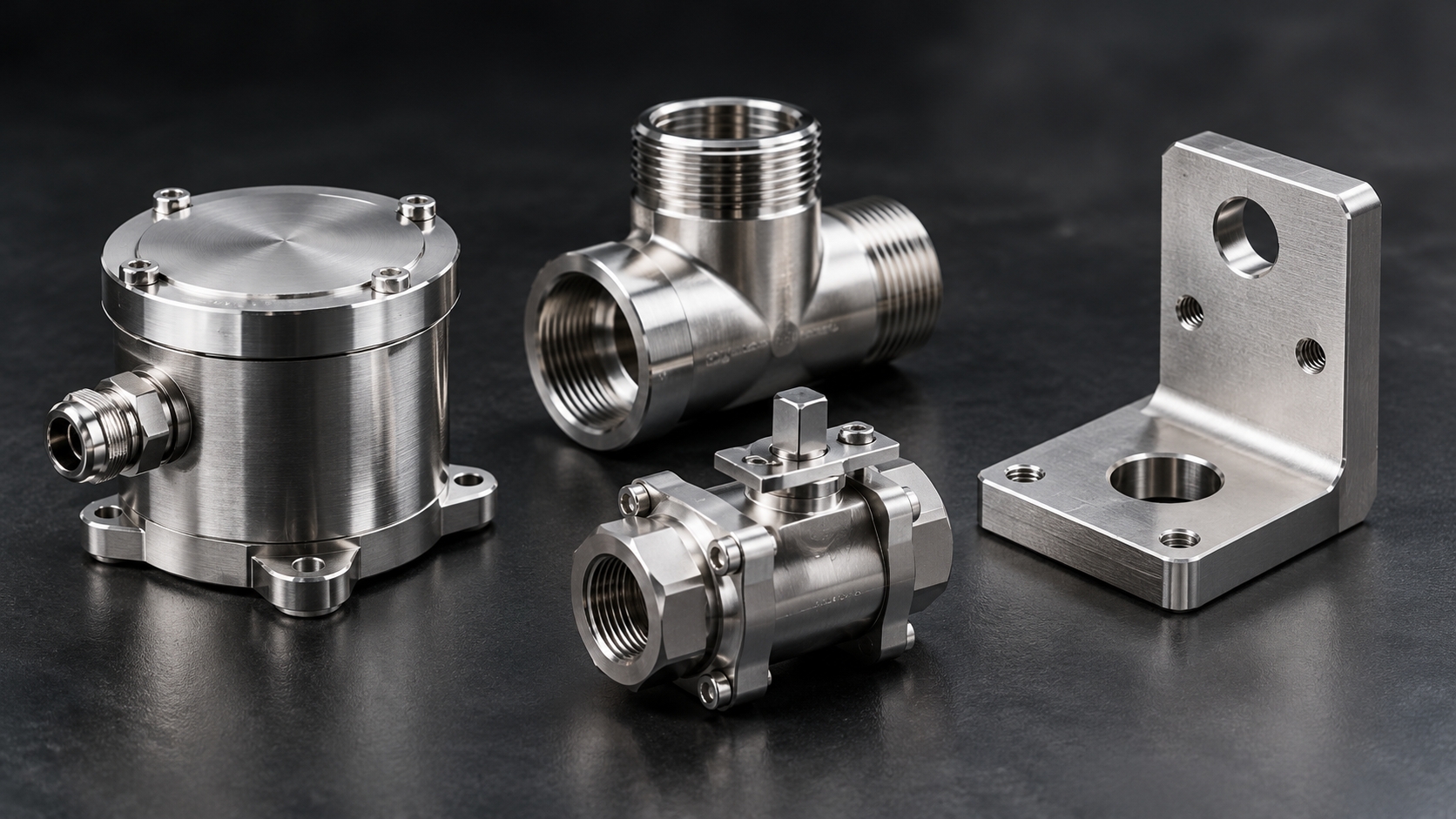
Boraco has been precision CNC machining in Dongguan since 2013 — mold cavities and cores, shear edges, inserts, trimming fixtures, and post-mold secondary machining for compression-molded parts. We also machine the same part families directly: aluminum, stainless, titanium, brass, and engineering plastics.
Read more about us, or see our full CNC machining service range and China CNC machining capability.
Send your CAD for a free DFM quote — response within 12 hours →