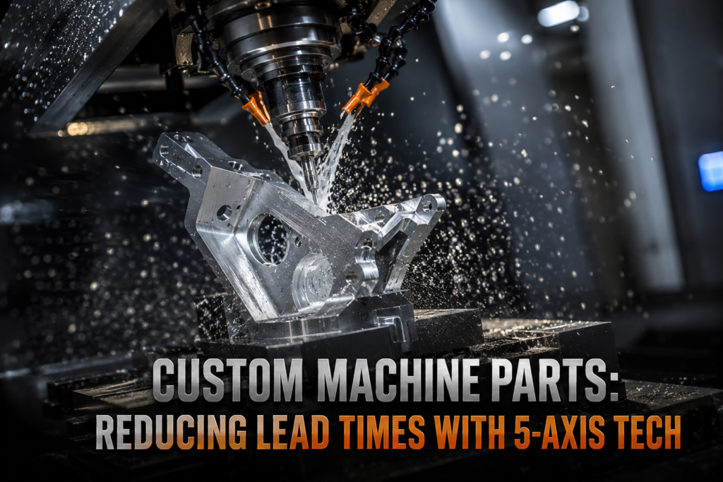
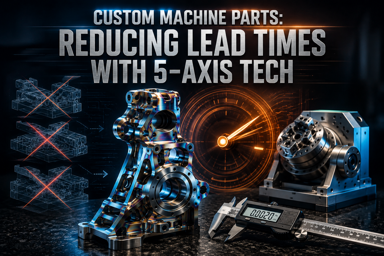
Custom Machine Parts: Reducing Lead Times with 5-Axis Tech
Procurement managers often face severe schedule delays. This usually happens when sourcing tight-tolerance parts through split production methods. However, using a **cnc custom** workflow on multi-axis machines solves this. This article shows how 5-axis tech reduces setups, stops errors, and shrinks lead times.
The Challenge of Traditional Machining in Procurement Cycles
In the procurement world, machine speed is rarely the main issue. Instead, the real bottleneck comes from non-cutting tasks. For example, building fixtures, managing multiple setups, and performing mid-stage inspections take up too much time. When sourcing a **custom machine** part on standard 3-axis mills, operators must flip the raw block many times. Consequently, each turn introduces human error and slows down delivery schedules.
Why Manual Part Flipping Causes Delays
Every time a worker flips a part, they must reset the work coordinate system manually. As a result, this process causes minor alignment errors to stack up across part features. For precision **custom metal** projects, these constant adjustments extend setup times from hours to days. Therefore, labor costs rise and factory output slows down significantly. In addition, manual intervention increases the risk of making scrap parts, which causes further shipping delays.
The Hidden Costs of Idle Work-in-Progress
Furthermore, moving parts between different machines creates idle time. Work-in-progress parts often sit on shelves waiting for an open machine. If you order complex **custom steel fab** projects, these handling delays pile up fast. Ultimately, avoiding these multi-setup steps is the best way for procurement teams to cut down volatile lead times. By choosing advanced production methodologies, you keep your parts moving forward continuously.
How 5-Axis Technology Accelerates CNC Custom Production
Simultaneous 5-axis machines eliminate these setup bottlenecks completely. They move the cutting tool along three linear axes and two rotational axes at the same time. Because of this, the tool can reach the raw block from almost any angle in one single operation. Therefore, when running a complex cnc custom project, the mill cuts deep pockets and angled holes without manual flips.
Eliminating Multi-Station Downtime
First, this single-station method reduces non-cutting time significantly. Machinists can switch from rough profiling to deep undercuts smoothly. Consequently, you do not have to wait days for custom jigs to be built for each side of the part. Instead, a universal setup handles the entire job. This change alone can shave up to 50% off the initial manufacturing schedule.
Maximizing Cutting Tool Rigidity
Second, because the tool can get closer to the part, workshops can use shorter and stiffer cutting tools. Shorter tools do not bend or vibrate as much under heavy loads. As a result, programmers can run faster spindle speeds and higher feed rates. This speeds up material removal without hurting surface quality. For a quick review of your multi-axis project, you can contact our team through our Contact Page.
Geometric Dimensioning and Tolerancing (GD&T) is a system of symbols used on engineering drawings. It explicitly specifies the exact allowable variation of geometric features. Governed by international standards like ASME Y14.5, it defines features like true position and flatness. In 5-axis machining, GD&T is critical. It allows features on opposite sides of a part to link to the same datum plane in a single setup. Therefore, it guarantees absolute accuracy that manual turning cannot match.
| Performance Metric | Traditional 3-Axis Processing | Simultaneous 5-Axis Processing | Impact on Procurement Lead Time |
|---|---|---|---|
| Fixturing Requirements | Multiple specialized jigs (3 to 6 distinct setups) | Single universal fixture or hydraulic vise | Saves 48 to 72 hours in jig preparation |
| Cumulative Setup Error | ±0.05 mm to ±0.12 mm (due to datum shift) | Within machine volumetric limits (≤±0.005 mm) | Eliminates part rejection and re-machining cycles |
| Surface Roughness ($R_a$) | 1.6 μm to 3.2 μm (requires hand finishing) | 0.4 μm to 0.8 μm (as-machined finish) | Eliminates secondary off-machine polishing phases |
| Spindle Utilization Rate | 35% to 50% (due to manual alignment cycles) | 75% to 85% (continuous automated cutting) | Reduces total factory processing duration by 40% |
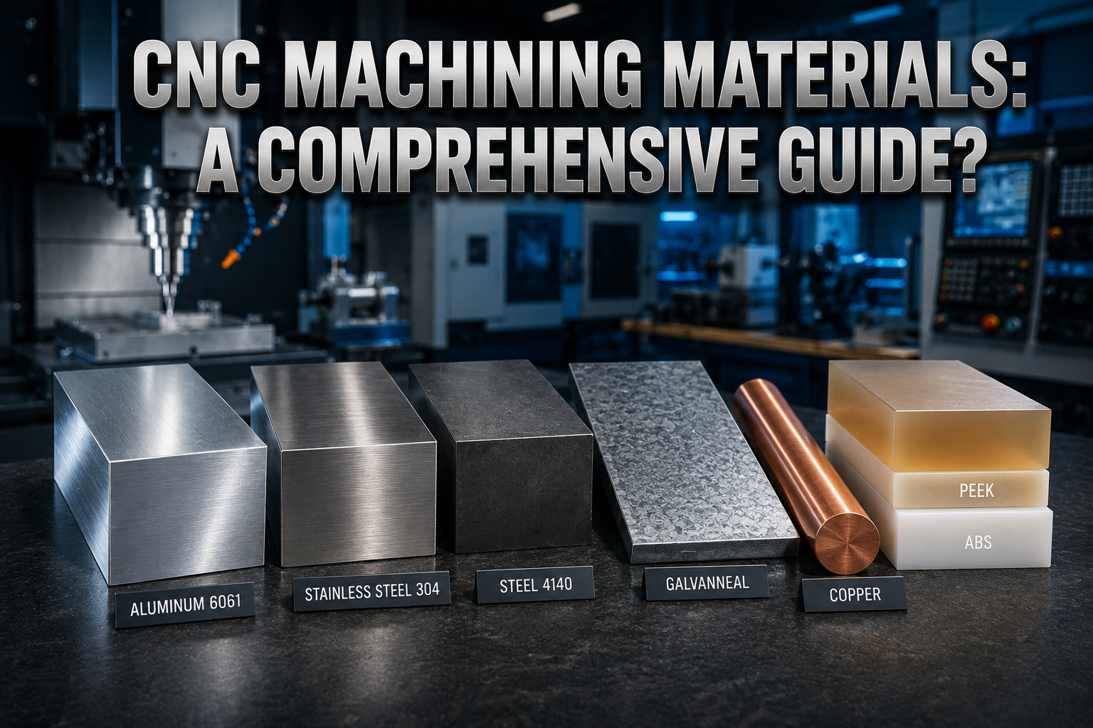
Material Selection and Design Considerations for Custom Metal CNC
Material choices directly impact tool paths and spindle feed rates. For instance, sourcing structural items like **custom steel** parts requires careful planning. Alloys like 316L stainless steel harden very quickly under heat. Therefore, they need rigid workholding and precise cutting angles to prevent surface damage. If the tool path is wrong, the material will ruin the cutting edge quickly.
Machining Tough Alloys vs. Light Metals
However, light aluminum alloys behave differently. Materials like 6061 aluminum allow for very high cutting speeds. Consequently, machining times drop significantly when utilizing these alloys for a **custom metal cnc** order. But you must still manage heat. Even though aluminum is easy to cut, improper cooling can cause thin walls to warp. Therefore, choosing the right material matches your speed goals with part stability.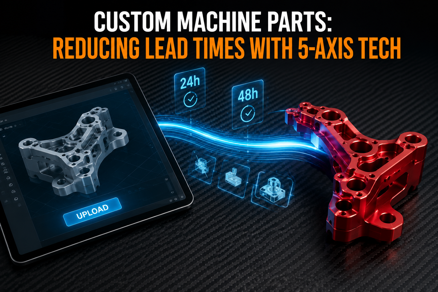
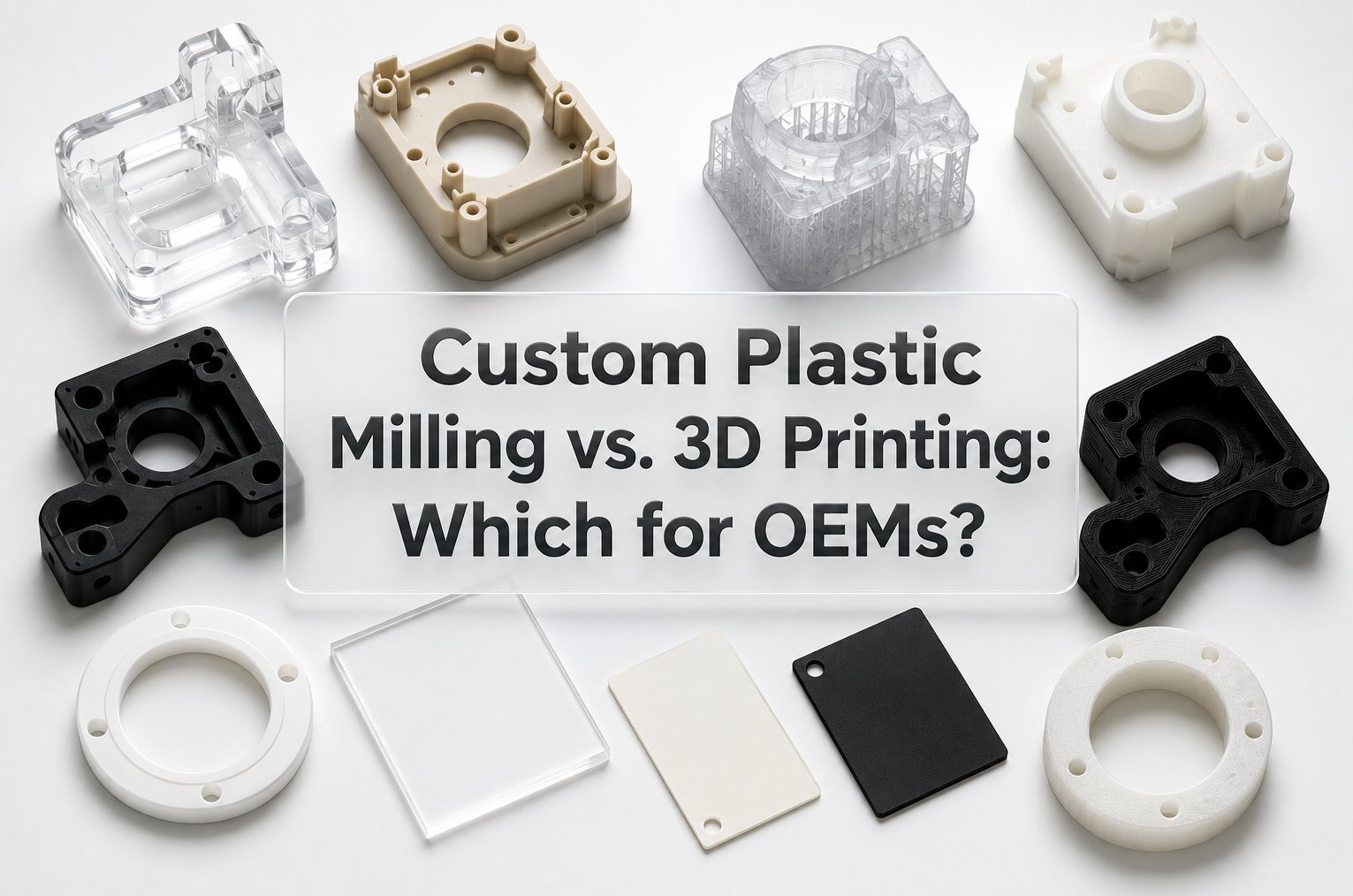
Optimizing Enclosures for Electronics and Plastics
On the other hand, electronic applications need different material strategies. For example, a housing might need to protect a **custom pcb** or a **custom made pcb** array. To shield these systems from interference, shops machine thin-walled enclosures out of **custom cut metal** blocks. Alternatively, if your project needs optical clarity, you can use **custom acrylic** sheet stock or specialized **custom plastic** like PEEK. However, these plastics require unique cooling to avoid melting during the high-speed milling process.
Standard Form Factors Reduce Prep Cycles
To keep costs low, always design parts around standard material sizes. For example, matching your design to standard **custom sheeting** or **custom cut steel** plates saves a lot of time. As a result, you spend less time cutting away bulk material. This approach directly lowers your lead times. Furthermore, sourcing standard shapes reduces the time spent waiting for custom raw stock deliveries.
| Material Category | Common Engineering Grade | Machinability Index (%) | Optimal 5-Axis Feed Optimization Strategy | Achievable Tolerances |
|---|---|---|---|---|
| Aluminum Alloys | 6061-T6 / 7075-T6 | 70% to 80% | High-speed trochoidal milling, dry/MQL cooling | ±0.005 mm |
| Stainless Steel | SS304 / SS316L | 40% to 50% | Constant chip load control, high-pressure coolant | ±0.010 mm |
| Carbon/Alloy Steel | AISI 1045 / 4140 | 55% to 65% | Rigid indexable face milling, balanced cutting speeds | ±0.008 mm |
| Engineering Plastics | PEEK / Delrin (POM) | 85% to 100% | Sharp polished carbide inserts, high chip evacuation | ±0.020 mm |
Optimizing the Transition from Custom STL Files to Production
The speed of a **custom machine** project also depends on your digital design files. Sourcing managers frequently send **custom stl files** during the quoting stage. These files work well for visual **custom 3d** printing or basic modeling. However, they use flat triangles to build shapes instead of true mathematical curves. This limitation creates problems for precision cutting machines.
Why STL Files Slow Down Quoting and Tooling
Therefore, CAM programmers must spend extra time converting these mesh files back into clean solid models like STEP files. This conversion process can delay engineering reviews by several days. If you provide native solid models along with 2D drawings from the start, the software can generate toolpaths much faster. Consequently, production begins without unnecessary administrative delays.
Linking Printed Circuit Boards with Enclosure Milling
This smooth digital workflow is critical when metal housings must fit internal electronics perfectly. For example, before you order custom pcb boards, your structural enclosures must align exactly with the board layouts. If the electronics change, parametric solid files let engineers update the custom cnc parts designs quickly. This agility keeps your **custom parts cnc** production on track. Ultimately, it prevents expensive rework and keeps your project on schedule.
Evaluating China CNC Machining Suppliers for Lead Time Reliability
Global sourcing requires a smart evaluation plan that looks beyond cheap unit prices. Sourcing teams must carefully review the technical skills of potential china cnc machining suppliers. First, make sure they hold certified ISO 9001:2015 qualifications. This step ensures strict quality management from raw material arrival to final delivery.
In-House Tooling vs. Subcontracting Risks
Second, look for suppliers that handle all manufacturing steps under one roof. Choosing a facility that offers **china machining**, precise turning, and finishing services keeps your project moving smoothly. If a shop subcontracts work, it introduces shipping delays and communication errors. By keeping everything in one shop, you protect your delivery dates. Furthermore, internal communication between teams is much faster.
Digital Inspection Tools Verify Part Accuracy
Finally, clear technical communication is essential for smooth international production. Reliable shops use digital inspection tools and coordinate measuring machines (CMM) to provide clear data reports. These automated tools check parts quickly against your original CAD designs. Partnering with an engineering-focused shop ensures your complex **custom cnc** orders arrive exactly on schedule. To learn more about our quality control tools, you can explore our about our team page.
Conclusion
In conclusion, shifting to 5-axis machining removes the manual setup delays that slow down part procurement. By finishing parts in a single operation, you get tighter tolerances and faster turnarounds. Therefore, to secure your supply chain, send your designs to Boraco Machining today to Request an Expert Technical Quote.
Frequently Asked Questions
Why is simultaneous 5-axis machining faster than traditional 3-axis milling for complex parts?
Simultaneous 5-axis machining moves the tool and the part along five axes at the same time. Because of this, it reaches almost every surface in a single setup. Traditional 3-axis milling requires workers to stop production and turn the part manually. Consequently, this manual work adds substantial downtime and extends lead times.
Can I use STL files directly to generate high-tolerance CNC custom toolpaths?
Generally, no. STL files represent surfaces using small, flat triangles. This structure lacks the precise mathematical curve data needed for tight tolerances. Therefore, engineers prefer formats like STEP or IGES files. These formats allow the programming software to calculate smooth, exact paths for the cutting tool.
How does single-setup manufacturing improve geometric dimensioning and tolerancing (GD&T) results?
Single-setup manufacturing cuts multiple features without releasing the part from its clamp. As a result, it completely eliminates datum shift, which is the tiny movement caused by re-clamping a part. This approach ensures that true position, flatness, and angles remain perfectly aligned to your engineering drawings.
What quality certifications should I check when vetting overseas CNC machining suppliers?
Sourcing teams should look for active ISO 9001:2015 certifications. This certificate ensures the shop uses reliable quality control and tracks raw materials accurately. Furthermore, for electronic assemblies, verify CE and RoHS compliance. These standards guarantee that materials meet international environmental and safety rules.